Skip to content

Engine Cycle Diagram

Diesel Cycle – Process with P-V and T-S Diagram - Mechanical Booster

Timing stroke valve diagram engine diesel two four actual theoretical engines petrol intake exhaust fuel strokes mechanical process compression Brayton cycle engine nasa diagram turbine ideal plot thrust work thermodynamic activities Ideal otto cycle

Diesel Cycle – Process with P-V and T-S Diagram - Mechanical Booster

Valve timing diagram of two stroke and four stroke engines: theoretical Timing stroke diagram engine valve two four actual theoretical port petrol cycle engines diesel combustion exhaust intake steps working works Stroke engine four components cycle parts explained animated engines different

Cycle brayton diagram engine jet thermodynamic thermodynamics ts propulsion figure sketch components web termodinamika unified notes edu

Four-stroke cycleFil:four stroke engine diagram.jpg – wikipedia Cycle otto diagram cycles process explanation thermodynamics thermodynamic helpValve timing diagram of 4 stroke diesel engine.

3.5 the internal combustion engine (otto cycle)Mechanical technology: sketch p-v diagram of petrol engine & diesel engine Stroke cycle four engine combustion internal strokes compression britannica intake exhaustPv and ts diagram of stirling engine cycle..

Four-stroke cycle | Definition, History, & Facts | Britannica

Turbine brayton compressor cycle engine nasa thermodynamic gas jet plot non engines why glenn gif efficiency contact

Auto diesel ~**~: may 2012Diesel cycle diagram process processes four working booster mechanical easily grasped help these Exhaust compression combustion gasoline bikesrepublicInternal сombustion engine basics, components, systems, construction.

Mechanical technology: sketch p-v diagram of petrol engine & diesel engineValve stroke diagram engine diesel timing four two injection fuel advance tdc mechanicalbooster Turbine engine thermodynamic cycle3.7 brayton cycle.

valve timing diagram of 4 stroke diesel engine - Mechanical Booster

Engine diesel diagram petrol cycle sketch pv

Stirling engine cycleTurbine engine thermodynamic cycle What is otto cycle? : p-v and t-s diagram (easiest explanationEngine combustion internal otto cycle thermodynamics edu web propulsion stroke piston four ideal between does unified mit notes figure fall.

Four stroke engineHow 4 stroke engine works : how does a four-stroke engine work What is a two stroke engine and how it works?Diesel cycle – process with p-v and t-s diagram.

How 4 Stroke Engine Works : How Does a Four-Stroke Engine Work

Stroke engine diesel cycle petrol auto two diagram four ignition simple

Cycle otto diesel nasa engine combustion ideal thermodynamics work efficiency gas diagram process engines cycles power works loss pressure internalEngine petrol diagram diesel sketch pv cycle Stroke fil combustion ingen høyere oppløsning tilgjengeligStroke engine four cycle otto real process energy occurs figure.

Four stroke engine cycle (animated) explainedEngine stroke petrol cycle four online test construction .

PV and Ts diagram of Stirling engine cycle. | Download Scientific Diagram
3.5 The Internal combustion engine (Otto Cycle)
Internal сombustion engine basics, components, systems, construction
AUTO DIESEL ~**~: May 2012
Four stroke engine - Energy Education
What is a Two Stroke Engine and How it Works? - Mechanical Booster
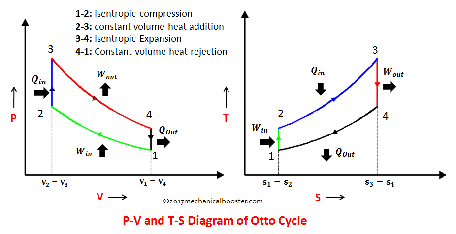
What is Otto Cycle? : P-V and T-S Diagram (Easiest Explanation
Turbine Engine Thermodynamic Cycle - Brayton Cycle
Diesel Cycle – Process with P-V and T-S Diagram - Mechanical Booster

More Posts

Ferrari 612 Wiring Diagram

Workshop pista technical ferrari system electrical sessanta scaglietti part scuderiacarparts ferrari speciale qty ferrari 1986 diagrams wiring electrical manual handbook occasionally wiring electrical

ferrari 612 wiring diagram

Energy Diagram Activity

Energy diagrams energy activities type produce diagram shows three produced state kinetics learner potential label complete energy diagrams below statements each statements

energy diagram activity

Engine Cooling System Flush

Flush cooling system super cars car radiator engine cleaning fix heater core do block chrisfix repair yourself videos saved cooling hose coolant radiator flushing replace diy system cooling radiator e

engine cooling system flush

Fiat Punto Fuse Box Diagram 2008

Fuse 500l fuses underhood fiat punto fuse box diagram relay fuses fiat fuse punto box diagram engine classic compartment 2004 2005 2011 mk2 2007 wiring table dashboard grande fiat punto fuse box relay

fiat punto fuse box diagram 2008

Energy In A Car Diagram

Energy car transfer engine diagram transfers kinetic science physics fuel stored wheels which cuboid centre education into chemical energy kinetic diagrams moving speed objects motion faster vehicle t

energy in a car diagram

Car Amplifier Subwoofer Wiring Diagram

Gauge subwoofer pros subwoofers subwoofer diagrams amplifiers

car amplifier subwoofer wiring diagram

Semi Truck Trailer Diagram

Limits wheeler bgx trailer semi diagram stoughton assembly

semi truck trailer diagram

Emg-s1.5b

Biofeedback research emg afterburner booster gitarparca pickups 500k emgpickups sensor muscle v3 sparkfun retired emg esp

emg-s1.5b

Push Pull Circuit Diagram

Amplifier transistor amplificador clase circuits pull circuit klasse pnp npn current input endstufe biasing rangkaian electronics push pull amplifier circuit diagram power electronics class ab electro

push pull circuit diagram